Support Forum
Unable to resolve an LVS error
Ted
Saturday 11th December 2021
Attachments:
(only for registered users)
 res_route.GDS
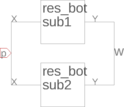
Attached are some designs using the openCellLibrary. I ran the layer from the Utilities menu before making these. I was having problems with a more complicated design, so I made this toy design to try to isolate the problem. First, delete all of the 'Generated with the LayoutEditor (This message will NOT added in any commercial version of the LayoutEditor.)' messages. Then, open res_top_unmirrored, and in the Extraction pane run 'Build Connections' then 'Layout Versus Schematic'. You should see the two messages: > connection missing sub1/X > > connection missing sub2/X If you delete the text label 'p' from the layout and re-run 'Build Connections' then 'Layout Versus Schematic' you should see the error: >external node p not labeled If you now delete the pin 'p' from the schematic and in the layout and re-run 'Build Connections' then 'Layout Versus Schematic' you should see the message >No errors. The 'No errors.' results seems to indicate that LayoutEditor can tell that sub1/X and sub2/X are connected to each other. The 'external node p not labeled' results seems to indicate that my pin in the schematic is recognized. Since the 'external node p not labeled' results goes away when I add a text label in the layout, I'm assuming that I'm properly labelling that node in the layout. So how can I resolve the 'connection missing' errors when I have a pin in the schematic and a corresponding label in the layout?
Saturday 11th December 2021
Attachments:
(only for registered users)
res_route.GDSAttached are some designs using the openCellLibrary. I ran the layer from the Utilities menu before making these. I was having problems with a more complicated design, so I made this toy design to try to isolate the problem. First, delete all of the 'Generated with the LayoutEditor (This message will NOT added in any commercial version of the LayoutEditor.)' messages. Then, open res_top_unmirrored, and in the Extraction pane run 'Build Connections' then 'Layout Versus Schematic'. You should see the two messages: > connection missing sub1/X > > connection missing sub2/X If you delete the text label 'p' from the layout and re-run 'Build Connections' then 'Layout Versus Schematic' you should see the error: >external node p not labeled If you now delete the pin 'p' from the schematic and in the layout and re-run 'Build Connections' then 'Layout Versus Schematic' you should see the message >No errors. The 'No errors.' results seems to indicate that LayoutEditor can tell that sub1/X and sub2/X are connected to each other. The 'external node p not labeled' results seems to indicate that my pin in the schematic is recognized. Since the 'external node p not labeled' results goes away when I add a text label in the layout, I'm assuming that I'm properly labelling that node in the layout. So how can I resolve the 'connection missing' errors when I have a pin in the schematic and a corresponding label in the layout?
Ted
Saturday 11th December 2021 I don't think a can attach LEL or LES files here, so I just emailed them to you
Saturday 11th December 2021 I don't think a can attach LEL or LES files here, so I just emailed them to you
Jürgen
LayoutEditorFull
Saturday 11th December 2021
Attachments:
(only for registered users)
your-schematic.png

correct.png
the issue is in the schematic:  If you look closely the wire between the two x pins of the subcircuit is not connected with the port. There is no dot connecting that wire in the middle with the port *p*. The correct schematic should look like:  I guess you have created the port first and then drawn the wire in one step over the port without making a stop there.
LayoutEditorFull
Saturday 11th December 2021
Attachments:
(only for registered users)
your-schematic.png
correct.png
the issue is in the schematic:  If you look closely the wire between the two x pins of the subcircuit is not connected with the port. There is no dot connecting that wire in the middle with the port *p*. The correct schematic should look like:  I guess you have created the port first and then drawn the wire in one step over the port without making a stop there.
Ted
Saturday 11th December 2021 Ah, thanks for the response. I've actually been adding the port on top of the existing wires. I'm surprised I didn't come across a problem earlier.
Saturday 11th December 2021 Ah, thanks for the response. I've actually been adding the port on top of the existing wires. I'm surprised I didn't come across a problem earlier.